| |
Inexpensive Precision Frequency Standardby Neil Robin, WA7NBF
|
Create a homebrew 10 MHz frequency standard for Frequency Counters under $70.00. Accuracy better than 0.2 PPM over a years time!
One thing that’s always handy around the ham shack is a frequency counter to check accuracy of your transmitters. The trouble is a highly stable oscillator which is usually out of reach for most amateurs is needed as the counters reference. What follows is an approach that you can put together for under $70.
I bought a used low cost counter, Goldstar Model FT-2130 a few years ago on e-bay to measure the frequency of all my handheld and base station radios for HF, VHF and UHF. I also build foxhunting systems which typically use old synthesized radios so I wanted to be sure they meet specifications before putting them to use. The counter has a ÷10 prescaler so it can be used up to 1.3 GHz. This is more than enough for all the amateur bands including 23 cm.
One of the first things you ask is how good is the time base for the counter? You can't set a transmitter frequency accurately if you don't have confidence in the reference you're using. Just as I thought, my built-in counter oscillator was low in frequency by 2.8 PPM (parts per million) after it warmed up for a twenty minutes. It’s a type called TCXO (temperature compensated crystal oscillator). They're relatively cheap and that’s why you find them in medium precision devices such as counters. I had no idea what the drift characteristics would be over time, effects of line voltage or as temperature varied? It could be much worse than 2.8 PPM in routine situations. In short, I didn't really know if this measured error was good or bad nor how it varied with environmental factors?
Digital frequency counter accuracy is influenced by several factors. But, you should know how much accuracy you need for a given measurement. You can go crazy chasing something you really don't need.
For counters:
Item #1 usually has the most influence in measurements when a long TB is used and input frequency is high. When high accuracy is needed, use as long a TB as practical, 10 seconds being common but 1 second can be used in some circumstances. Some counters have a 100 second time base but unless you have the reference oscillator to compliment it, you probably don't need it. For very low frequencies, audio for example, a period measuring counter, using period averaging, gives superior results.
Item #3 and 4 comes into play when you display too few digits of resolution. Most inexpensive counters have ±1 count error on the LSD. This comes about because the reference oscillator and the input signal are usually asynchronous with undetermined phase relationship. More expensive counters can reduce this error to 1/2 the amount.
In frequency counter measurements, the LSD resolution limits what you can achieve. Each count of the LSD gives the error in PPM:
| PPMper count | = | (Prescale Factor) x 106/(Time Baseseconds x Fin hertz) (1) |
| Where | ||
| Prescale Factor | = |
Usually 1, 2, 10. Amount the input signal is divided down before the first digit, LSD, is displayed. |
| Time Baseseconds | = | Duration of the TB or measurement gate. Usually 0.1, 1, 10 or 100 seconds |
| Fin | = | Input frequency in hertz |
You want the PPMper count value to be as small as possible to gain the best resolution. Examining equation (1), it’s clear that you want to avoid prescalers if you can and increase the Time Base to as long as possible. Ten seconds is usually the practical limit. At 147 MHz with a divide by 10 prescaler using 10 second TB yields 0.0068 PPM/count. This is significantly better than needed and it’s clear that the oscillator stability will be the limiting factor in overall accuracy.
It's rare today to find a counter with a ÷2 prescaler but if so; the TB selection will usually be increased by 2X to correct the display.
When estimating the needs of radio transmitters, it’s usually the channel spacing that controls the oscillator stability requirements. Two meter radios have channel spacing in their synthesizer of 5 kHz. You should not allow frequency instability beyond 5 KHz/2 or ±2.5khz, preferably less. At 147 MHz this works out to:
| PPM | = | ERRORhz x 106/(Base Frequencyhz) (2) |
| |
= | ±2.5 x 103 x 106/1.47 x 108 |
| = | ±1.70 x 10 = ±17 PPM |
2.8 PPM as measured above isn't bad for a low cost counter if all you need is 17 PPM. Of course other bands will have different spacing requirements so this target would be band specific. 445 MHz with 5 KHz spacing requires stability of ±5.6 PPM.
I really wanted something better that I could trust over a long period of time. One solution is most counters have a rear jack for an external reference signal. This is the usual way to solve this problem, particularly in a lab environment. Just plug in the "house frequency standard" and off you go. One problem to overcome is the frequency needed? Most counters require 10 MHz as a standard reference plus adequate amplitude to drive their divider circuits.
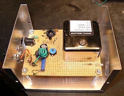
I purchased a high precision OCXO (Oven Controlled Crystal Oscillator) on e-bay that met all my specifications with flying colors but the signal output was 5 MHz. They sell for about 35-$40 and are brand new. Oven control means that the crystal and key oscillator parts are inside a very small oven in the main housing. In this case, it’s kept at 80° C.
| Frequency | 5 Mhz |
| Temperature Stability | ±1 x 10⁻⁷, -30 to +70º C (±0.1 PPM) |
| Aging | 2.5 x 10⁻¹⁰/day or
for 365 days = 9.12 x 10⁻² PPM/year |
| Frequency vs Supply Voltage, 12 Volts ±5% | 2 x 10⁻⁹/percent (2 x 10⁻⁵ PPM) |
| Output | Sinewave, 1.5 volts P-P |
Of course, when you buy something without knowing its history or the integrity of specifications, you’re exposed to risks. For something as important as a frequency reference, you'd like to be sure its stable. The best way I've found is to recheck its performance a number of times over a year and note any serious deviation, particularly when they challenge published specifications. When things are sold "new" at auction such as e-bay, they may be deficient in some way and unusable for the original application or they may have just been excess. Buyer beware, you may have a good deal or not.
I started checking its accuracy, at least once a month, and
so far its better than my resolution capability of the error
signal. I'll go to once or twice a year once I build confidence
that its making specifications or is stable within my needs. This
builds confidence that it’s really as stable as
they
claim. Notice that ambient temperature extremes and aging
have
about equal effect; far better than needed for an oscillator in amateur
service. A copy of the complete specifications can be found here.
The Vectron oscillator was purchased from
Alltronics which usually had
several models but their source seems to have dried up recently. By
maintaining a search on e-bay for OCXO's, you should hit pay dirt
soon. New, these oscillators sell retail for $250 and up.
The task is to interface the OCXO to the counters input standard frequency and amplitude requirements. Since the counter expects 10 MHz and the oscillator produces 5 MHz, some type of frequency multiplier is needed to give a doubler function. Most would consider a phase locked loop (PLL) which can be implemented with a single IC and a few components. A problem with this approach is that if the 5 MHz oscillator fails the PLL will still run and generate an erroneous signal near 10 MHz that is uncalibrated. Not a good idea for a frequency standard. You can implement an "unlock" detector but this seems a roundabout way to solve the problem. Another concern was that many PLL's don't generate clean sinewaves which I wanted.
Years ago I use to build multiplier circuits for stable UHF signal references and wondered if I could still do it even though this was only 10 MHz? Figure one shows the approach I used. A doubler, T1 and D2-D3 injects a signal (now 10 MHz) into the circuit, Q1, that would normally be a colpitts oscillator but purposely has limited feedback so as not to oscillate w/o the injected signal. It might be best called a high "Q" bandpass filter. If the 5 MHz source were to fail, the Q1 circuit would also fail and we'd have no output, a desirable outcome for a frequency reference.
 |
| Figure 1 |
The schematic excluding power supply can be found here.
T2 along with C2 and C4 form a 10 MHz resonant circuit. Injection
of the
voltage doubler, a 10 MHz signal from T1 is via 1/2 turn winding into
the torid
core, T2. The effective "Q" of this circuit can be increased by
splitting C4 into two series parts with the common point connected to
the
emitter. This creates a Colpitts oscillator and with enough
feedback, can
self-oscillate even when the Vectron oscillator is disabled. I
have also
considered using a 10 MHz crystal as the resonant element but again be
careful
of feedback because of its very high "Q".
You might notice that I used three torid cores for the transformers
of this circuit. That’s not by necessity but only because I enjoy
winding
my own inductors and experimenting with values used. T2 and T3
could just
as easily be made with plain inductors that are reasonably low
loss. T2
could be implemented with a 5 uh inductor and a 1/2 turn wound over it
for
coupling. The circuit is tuned by adjusting C2 for maximum output
signal.
It would also be a good test to check to be sure the output drops to
zero when
the Vectron oscillator is disconnected to be
sure no
self oscillations are present.
The entire circuit is run off of +12 VDC. I designed it that
way for several reasons:
OK, how do I calibrate a secondary frequency standard? Their are two common ways for most amateurs.
Number 2 is the only practical solution for most of us. Their are other frequencies where WWV broadcasts references but 10 MHz is easiest to work with if your secondary is also 10 MHz. You'll need suitable propagation at the time of calibration but its broadcast from more than one place in the world.
 |
| Figure 2 Using WWV as a
reference. Radio would be tuned to near 10 MHz |
The idea is to beat the incoming WWV or WWVH signal with your new
secondary standard and listen for the beat frequency which will be the
error
signal. See figure 2. Use the AM setting for demodulation
rather than SSB since
the
carrier injection will add confusion. The receiver is only needed
to hear
the weak signal from WWV. You don't rely on the accuracy of any
internal
oscillators of the radio. The secondary standard
signal
must be adjusted to a low level using attenuators and about the same
level as
WWV so as not to
over power the receiver
front end and block WWV .
A few problems must be considered and addressed:
If you have a friend that works at a
communications lab
or facility, they probably have a "house standard" that could be used
to check your standard from time to time. Be sure it’s really
better and
well maintained itself! As these oscillators become more and more
precise, they require careful handling which means no physical shock or
wide
changes in temperature. They may not recover from temporary abuse
and that
includes your standard. Never power down a standard
oscillator if you can avoid it. Some can take days to recover
to full specifications. For these reasons, I'd rather use WWV and
leave my standard sitting on the shelf powered up at all times.
Verifying performance with WWV is showing that the standard is quite stable. So far, I've had less than 1 Hz beat frequency difference or "flutter" between the two signals. I leave it run 24/7 so that it has no induced thermal shock over its life. I use a Yaesu FT-757GX HF transceiver for the measurement.
The circuit is not an attempt for simplicity but to make it work with components I had available. To build it again, I would probably try a 10 MHz crystal filter to build the high "Q" circuit. Many variations are possible, please share any novel ideas you come up with.
Neil Robin
WA7NBF
neil@robin-wood.com